Difference between revisions of "Making scale designs on the computer"
m (Text replacement - "http://straightrazorpalace.com" to "https://straightrazorpalace.com") |
|||
| (5 intermediate revisions by 3 users not shown) | |||
| Line 29: | Line 29: | ||
Having said that, it is still possible to follow the same procedure using a digital camera, but you, yourself, will be responsible for setting up the shot properly (''This is essentially copy photography'') and then later the additional steps of resizing your image so that it prints out at the correct size in the real world. Any discussion of those techniques is definitely outside the scope of this article. So, moving right along…<br> | Having said that, it is still possible to follow the same procedure using a digital camera, but you, yourself, will be responsible for setting up the shot properly (''This is essentially copy photography'') and then later the additional steps of resizing your image so that it prints out at the correct size in the real world. Any discussion of those techniques is definitely outside the scope of this article. So, moving right along…<br> | ||
| − | <gallery caption=" | + | <gallery caption="Scanning the blade." widths="350px" heights="300px" perrow="2"> |
| − | File:Ignatz-making-scale-designs-computer04 scan interface.jpg|Here is a view of the scanner interface. There are so many scanner programs out there that yours is bound to be different. | + | File:Ignatz-making-scale-designs-computer04 scan interface.jpg|Here is a view of the scanner interface. Here is a view of the scanner interface. There are so many scanner programs out there that yours is bound to be different. This scan was not made with that white flip-up cover down behind the razor, so that the background appears black (the dark ceiling of the room, actually). This isn’t a great problem for us. In fact, we are also not concerned with color or even absolute sharpness of detail. What we want is essentially a silhouette to show us the shape of the blade and the location of the rear pivot hole. |
| − | File:Ignatz-making-scale-designs-computer05 scan.jpg|Here is the scanned image of | + | |
| − | File:Ignatz-making-scale-designs-computer06 cutout scan.jpg| | + | File:Ignatz-making-scale-designs-computer05 scan.jpg|Here is the scanned image of the blade. Pretty nice. |
| − | File:Ignatz-making-scale-designs-computer07 scale design.jpg| | + | File:Ignatz-making-scale-designs-computer06 cutout scan.jpg|For the purposes of this presentation, a photo retouch program was used to mask out and remove the black of the background. True enough, it isn’t necessary (as you will later see), but it will make the following graphics a bit more obvious. |
| + | File:Ignatz-making-scale-designs-computer07 scale design.jpg|The image has now been loaded into the vector (linework) program and it has been used as a background reference over which to design the scale form. This is a fairly straightforward razor scale form which fits fairly well to this particular blade. There are indicators added to show where the pins will go. These are marked very clearly with a centering “X” where the pins are, to help later on in the shop when one begins the drilling process. | ||
| + | |||
</gallery> | </gallery> | ||
| − | + | Covering all the different aspects of making good scales is not within the scope of this article aside from offering a few hints. | |
[[Image:Ignatz-making-scale-designs-computer08 detail arrows.jpg]] | [[Image:Ignatz-making-scale-designs-computer08 detail arrows.jpg]] | ||
| − | Never forget to make your scales wide enough so that the bottom of the blade has no chance to poke out and cut you when the blade is closed (see | + | Never forget to make your scales wide enough so that the bottom of the blade has no chance to poke out and cut you when the blade is closed (see '''‘A’''' and '''‘B’'''). |
| + | |||
| + | Designing scales on the computer this way allows us to ‘see’ the required clearance for the front wedge ahead of time. Note the two arcs in the linework, both centered on the rear pivot hole ('''‘D’'''). One arc just touches the absolute end of the razor blade. The second arc has a radius which is a slim 1/16” of inch wider. Having those arcs to look at is a good reference in allowing one to decide how far the toe of the scales have to extend in order to give a good, stable amount of area ahead of the toe of the blade for the wedge and front pin. | ||
| − | + | Notice the extension of the scales behind the rear pin ('''‘D’'''). When using Micarta we could actually make that shorter, but when using other materials like wood, plastic or bone this scale extension is a good thing as it adds strength and somewhat reduces the tendency of the scales to split around that hole. | |
| − | + | <gallery caption="Linework Layers and the Printout" widths="350px" heights="300px" perrow="2"> | |
| + | File:Ignatz-making-scale-designs-computer09 layers.jpg|Something to keep in mind is the appropriate use of the '''‘layers’''' features within your graphics programs. You can see that the elements of my drawing are arranged so that each has a separate layer. The original, scanned image is in the back (lowest layer) and the linework has been added on top of it. This keeps our image clean, organized and manageable. | ||
| + | File:Ignatz-making-scale-designs-computer10 layers OFF.jpg|We are also going to take advantage of the '''layer visibility''' feature. Just before printing this out to paper, we turn off the visibility of the layers with the arcs and the background photo so that those layers do not print. See, we didn’t really need to do any fancy work on that image as it is never actually used in the printout. Don’t forget to save your work. You might find that you have to print it out again. Remember that you can also take the form you developed here and scale it up or down, or subtly alter its form to fit other blades. | ||
| + | File:Ignatz-making-scale-designs-computer11 printout.jpg|Here is the printout of the scale form. All we have to do now is cut it out and stick it onto the scale material. You will notice that the scale form was duplicated within the linework program so that there are multiple copies printed out on the page. This means that you have extras in case you spoil your first cutout. You can also set aside the unused copies for later use. | ||
| + | File:Ignatz-making-scale-designs-computer12 ruler check.jpg|If you have any concerns that your printout does not match the size of your scanned object, then the best thing to do is run a size test. What you see below is a printout of a measuring tape which was scanned as a test object. The printout definitely matches the dimensions of the real-world object. Should you decide to use a digital camera instead of a flatbed scanner, you could include an object of known size (like a ruler) in the same shot as your razor blade. It will assist you in sizing the image correctly. | ||
| − | |||
| − | |||
| − | |||
| − | |||
| − | |||
</gallery> | </gallery> | ||
| − | Last of all, we are going to stick our printout onto the scale material. | + | Last of all, we are going to stick our printout onto the scale material. A very good adhesive for this purpose is rubber cement. It is inexpensive, does not stain, goes on easily and (more importantly) comes off easily when you no longer want it. |
| − | <gallery caption=" | + | <gallery caption="Cementing the printout onto the scales." widths="350px" heights="300px" perrow="2"> |
| − | File:Ignatz-making-scale-designs-computer13 rubber cement.jpg|Rubber cement can be used on only a single surface, but in doing so, you end up with a weak bond. We want something stronger. To this end, we will use the rubber cement in exactly the same way that one uses contact cement. We will brush it onto both surfaces to be joined. Let | + | File:Ignatz-making-scale-designs-computer13 rubber cement.jpg|Rubber cement can be used on only a single surface and directly sticking the two objects together while the cement is wet, but in doing so, you end up with a weak bond. We want something stronger. To this end, we will use the rubber cement in exactly the same way that one uses contact cement. We will brush it onto both surfaces to be joined. Let the rubber cement dry for about five or ten minutes. Then bring the two rubber cement coated surfaces together. Press firmly or even tap lightly with a soft, rubber hammer. When done correctly, it gives a bond that will hold up to sanding operations and will also hold quite well even when cutting the Micarta with a scroll saw. You will find that you can still pry the surfaces apart with relative ease when you are finished. And any leftovers of rubber cement can just be rubbed away with the fingers. |
| − | File:Ignatz-making-scale-designs-computer14 ready to cut.jpg|And here is the final result. The Micarta sheets have been rubber cemented | + | File:Ignatz-making-scale-designs-computer14 ready to cut.jpg|And here is the final result. The Micarta sheets have been rubber cemented together and the scale printout has been rubber cemented on top of them. |
</gallery> | </gallery> | ||
| − | + | Time to head off into the shop for the cutting, shaping and finishing. But that is for another article... | |
== Acknowledgements == | == Acknowledgements == | ||
| − | This article is based on original work by Ignatz<ref> | + | This article is based on original work by Ignatz<ref>https://straightrazorpalace.com/workshop/40416-making-scale-designs-computer.html</ref> |
== References == | == References == | ||
Latest revision as of 10:36, 17 February 2018
This is a presentation of some basic procedures for creating razor scale forms using the computer. Although almost everything in this article can be done using classic drawing tools on paper or card stock, a computer system does offer some advantages in that one’s work can be printed out numerous times, as well as altered and resized for use with other razors than the one for which they were originally intended.
Naturally, every single one of you reading this has some sort of a computer, be it Mac, Windows PC, Linux box or what have you. If, in addition to that, you have a printer and (hopefully) a flatbed scanner, then you have all the hardware required to do pretty much the same as as shown here for creating razor scale designs.
NOTE: These procedures will be covered only in a very broad and basic way, just showing you the steps which one goes through along with a few tips. It would be interesting to go into more detail, but you all have different computers, using different scanners, printers and graphics programs, so that it would just be impossible to cover them all within the a single article.
Which graphics programs to use is another large question. A very popular photo retouch program is the Adobe Photoshop. For vector work (linework) Adobe offers theIllustrator program. But these are personal choices and it must be admitted that the Adobe products have always been somewhat expensive. But we are not doing anything fancy here, so almost any programs worth their salt should do the job. There is even pretty good freeware available which will do everything we need to do for this project. Two freeware programs that can be recommended are The Gimp for photo retouching - www.gimp.org/ - and Inkscape for vector work - www.inkscape.org/
Let’s now turn our eyes to a sample razor to restore. The old scales are of some sort of wood. They are pretty worn and look somewhat oversized for this blade, although they are actually too short for the blade to close properly. We will replace them with a new set made from Micarta (cloth fiber embedded in epoxy resin).
By the way, take a look at those rivets. Wow, those are some oversized monsters! In truth, the pins are cut off nails and those round ‘heads’ are actually blobs of melted lead solder (ouch!). We will grab for a metal file, remove the rivets (and old scales) and continue with the article…

Here is the blade, removed from the scales. Notice that dimple slightly forward of the rear pivot hole. The scales were just slightly short and the man who put the wooden scales on this razor thought to redrill that hole so that he might move the blade back to give it a bit more room. He didn’t realize that a razor is made of hardened tool steel and is a pretty tough contender for ordinary drill bits. Other than that, the blade isn’t in such bad shape. We will need to spend a few quiet hours sanding and polishing to clean it up. But there are other articles here on the SRP forums which give you information about refinishing blades, so we will not go over it again here. Time to start designing some scales.

The first step is to put the blade down onto our flatbed scanner in order to get an image into the computer. Here is the blade lying on an Epson 2400 Color flatbed scanner.

Some of you might be asking, “Well, isn’t my digital camera good enough for this purpose?” Well, yes and no. A digital camera will take a fine picture, but has two characteristics which make it a little less than ideal for this purpose.
The first problem is that a camera does not take a truly ‘flat’ image like a flatbed scanner. There will always be problems with perspective and some amount of distortion due to the imperfect optics of camera lenses. A flatbed scanner – even a cheap one – will always spit out a flat, distortion-free image, which is what we want for our purposes.
The other problem with a digital camera is that one has no real idea of the size of whatever one has photographed. The brilliant thing about a flatbed scanner is that when we get an image out of it, that image already has, encoded within it, the physical size of the scan. This means that if you don’t change or somehow screw up that size encoding, you should be able to print out that scanned image and end up with a printout in the real world which is the same size of what you originally scanned. It is exactly this property that allows us to design a scale shape around the scanned image, spit it out onto paper and use that printout as a reliable cutting and drilling layout.
Having said that, it is still possible to follow the same procedure using a digital camera, but you, yourself, will be responsible for setting up the shot properly (This is essentially copy photography) and then later the additional steps of resizing your image so that it prints out at the correct size in the real world. Any discussion of those techniques is definitely outside the scope of this article. So, moving right along…
- Scanning the blade.
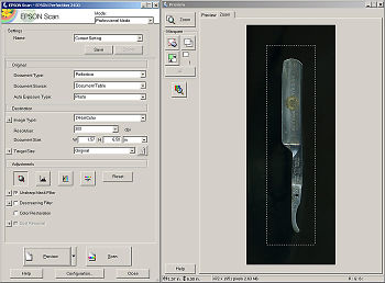
Here is a view of the scanner interface. Here is a view of the scanner interface. There are so many scanner programs out there that yours is bound to be different. This scan was not made with that white flip-up cover down behind the razor, so that the background appears black (the dark ceiling of the room, actually). This isn’t a great problem for us. In fact, we are also not concerned with color or even absolute sharpness of detail. What we want is essentially a silhouette to show us the shape of the blade and the location of the rear pivot hole.
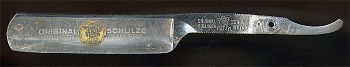
Here is the scanned image of the blade. Pretty nice.
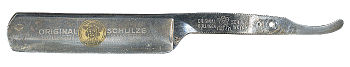
For the purposes of this presentation, a photo retouch program was used to mask out and remove the black of the background. True enough, it isn’t necessary (as you will later see), but it will make the following graphics a bit more obvious.
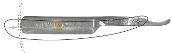
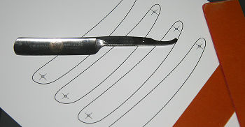
The image has now been loaded into the vector (linework) program and it has been used as a background reference over which to design the scale form. This is a fairly straightforward razor scale form which fits fairly well to this particular blade. There are indicators added to show where the pins will go. These are marked very clearly with a centering “X” where the pins are, to help later on in the shop when one begins the drilling process.


Covering all the different aspects of making good scales is not within the scope of this article aside from offering a few hints.

Never forget to make your scales wide enough so that the bottom of the blade has no chance to poke out and cut you when the blade is closed (see ‘A’ and ‘B’).
Designing scales on the computer this way allows us to ‘see’ the required clearance for the front wedge ahead of time. Note the two arcs in the linework, both centered on the rear pivot hole (‘D’). One arc just touches the absolute end of the razor blade. The second arc has a radius which is a slim 1/16” of inch wider. Having those arcs to look at is a good reference in allowing one to decide how far the toe of the scales have to extend in order to give a good, stable amount of area ahead of the toe of the blade for the wedge and front pin.
Notice the extension of the scales behind the rear pin (‘D’). When using Micarta we could actually make that shorter, but when using other materials like wood, plastic or bone this scale extension is a good thing as it adds strength and somewhat reduces the tendency of the scales to split around that hole.
- Linework Layers and the Printout
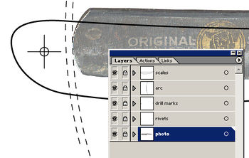
Something to keep in mind is the appropriate use of the ‘layers’ features within your graphics programs. You can see that the elements of my drawing are arranged so that each has a separate layer. The original, scanned image is in the back (lowest layer) and the linework has been added on top of it. This keeps our image clean, organized and manageable.
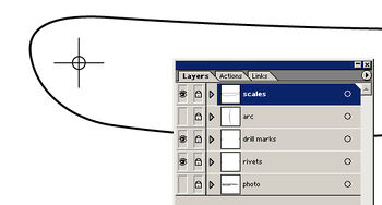
We are also going to take advantage of the layer visibility feature. Just before printing this out to paper, we turn off the visibility of the layers with the arcs and the background photo so that those layers do not print. See, we didn’t really need to do any fancy work on that image as it is never actually used in the printout. Don’t forget to save your work. You might find that you have to print it out again. Remember that you can also take the form you developed here and scale it up or down, or subtly alter its form to fit other blades.
Here is the printout of the scale form. All we have to do now is cut it out and stick it onto the scale material. You will notice that the scale form was duplicated within the linework program so that there are multiple copies printed out on the page. This means that you have extras in case you spoil your first cutout. You can also set aside the unused copies for later use.
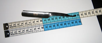
If you have any concerns that your printout does not match the size of your scanned object, then the best thing to do is run a size test. What you see below is a printout of a measuring tape which was scanned as a test object. The printout definitely matches the dimensions of the real-world object. Should you decide to use a digital camera instead of a flatbed scanner, you could include an object of known size (like a ruler) in the same shot as your razor blade. It will assist you in sizing the image correctly.


Last of all, we are going to stick our printout onto the scale material. A very good adhesive for this purpose is rubber cement. It is inexpensive, does not stain, goes on easily and (more importantly) comes off easily when you no longer want it.
- Cementing the printout onto the scales.
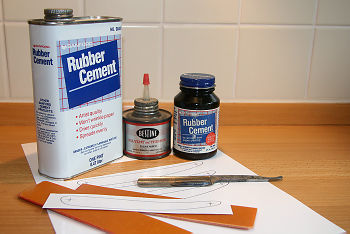
Rubber cement can be used on only a single surface and directly sticking the two objects together while the cement is wet, but in doing so, you end up with a weak bond. We want something stronger. To this end, we will use the rubber cement in exactly the same way that one uses contact cement. We will brush it onto both surfaces to be joined. Let the rubber cement dry for about five or ten minutes. Then bring the two rubber cement coated surfaces together. Press firmly or even tap lightly with a soft, rubber hammer. When done correctly, it gives a bond that will hold up to sanding operations and will also hold quite well even when cutting the Micarta with a scroll saw. You will find that you can still pry the surfaces apart with relative ease when you are finished. And any leftovers of rubber cement can just be rubbed away with the fingers.
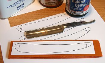
And here is the final result. The Micarta sheets have been rubber cemented together and the scale printout has been rubber cemented on top of them.


Time to head off into the shop for the cutting, shaping and finishing. But that is for another article...
Acknowledgements[edit | edit source]
This article is based on original work by Ignatz[1]